Requirement: To communicate between two Arduino Mega boards, about 7 meters apart, sending 6 bytes of data, and receiving 2 bytes of data back from the other board, keeping the supplies and grounds for both the supplies separate.
Procedure:
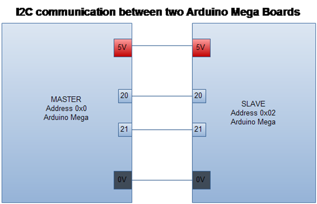
The first thing to do was to establish an I2C between two Arduino boards. This was done by taking two pieces of wire (short length, about 20mm), where both the boards had the same 5V and Ground.
This was done by first sending a byte from the Master to Slave and seeing if it reaches the Slave.
In the second instance, the slave processes that data, and sends a response back to the Master.
This was then repeated by sending 6 bytes to the Master, and getting one byte back from the Slave.
In the final part of this process, the Slave sends back two bytes in reply. Surprisingly, due to the nature of the Arduino WIRE library, this is a lot more complicated than it should be, or at least as intuition lends it to be. However, more on that in detail in the implementation.
Second part of the procedure is to implement the same bus over a wire length that is 7 meters long. Because of the nature of I2C, a bus extender is required. There are many of these on the market, and a P82B715 will be used to implement this.
Third part is implementation of the Galvanic Isolation. Analog Devices produce a few of those devices, and in this implementation, an ADUM1250 will be used.
Implementing I2C between two Arduino Boards
The main purpose of setting up an I2C bus was to get two Arduino Boards to talk to each other. Upon research of various communication options available, I2C stood out as a protocol that was already available and established, as well as simple to implement. It also only requires 2 wires (SDA and SCL) that are required for communication. More information about the I2C bus can be found in the reading material at the end of this post.
The Arduino communicates on the I2C bus via already dedicated pins. On the UNO they are pins 4 and 5 for SDA and SCL, while on the Mega they are 20 and 21. For other variations, the datasheet should be checked.
As long as the SDA of one is connected to the other, and SCL of one is connected to the other, the I2C Hardware implementation is complete. In the simplest implementation, the grounds of both Arduino Boards should be shared as well.
To use the I2C bus with the Arduino, the WIRE library, which is already a part of the Arduino IDE is used.
It should be noted that for this example/explanation the Arduino IDE 1.00 is used, and future as well as past versions may vary slightly. E.g. in the Arduino 22 IDE and below, the read() and write() commands are receive() and send() instead.
In this case, two Arduino software need to be prepared, one for the Master, which will govern the I2C Operation, and one for the Slave, which will receive data when the Master sends it, and sends data back to the Master, when the Master requests it.
First thing to do is import the Wire library in both the Master and the Slave.
#include
For the Master, in the setup() method, join the I2C bus:
Wire.begin(); // Join the I2C bus as Master (Address 0)
For the Slave, in the setup, the I2C bus has to be joined as a certain address. In our example, we assign it address 0x02. This address is a hexadecimal value, and can be anything between 0 and 127. Which also means up to 127 devices can be added to an I2C bus.
Wire.begin(2); // Join the I2C bus as Master (Address 2)
Then in the Master, the sending and receiving of data is implemented.
This is started by the Master declaring that it is about to send data to the specified address:
Wire.beginTransmission(2); // Transmit to device 2
Then the number of bytes that are to be sent are sent. In our case this is 6 bytes. It is easier to send them as an array of 6 bytes, which is why an array of 6 bytes was declared, and sent byte by byte.
// Transmit 6 bytes of outgoing:
Wire.write(outgoingByte[0]);
Wire.write(outgoingByte[1]);
Wire.write(outgoingByte[2]);
Wire.write(outgoingByte[3]);
Wire.write(outgoingByte[4]);
Wire.write(outgoingByte[5]);
After the operation is complete, the transmission is ended:
Wire.endTransmission();
After this operation is complete, request data from the Slave, which specifies the number of bytes required as well.
Then the data is stored into a couple of bytes using the read() command.
// Receive Data:
Wire.requestFrom(2,2);
incomingByte[0] = Wire.read();
incomingByte[1] = Wire.read();
And that is all there is to sending and receiving data via a Master.
A similar implementation is carried out in the Slave. The program specifies to call a method when it receives any data, and similarly it calls a method when it is requested to send any data.
While receiving data is the exact same as master, to send data, the outgoing information should be an array of the requested size (no. of bytes requested), where the bytes in that array have the required information.
So in the loop () method, specify which methods to call when I2C data is sent or requested:
// Call receiveEvent() when received.
Wire.onReceive(receiveEvent);
// Send Data to Master:
Wire.onRequest(sendInfo);
And the method to receive is quite simply reading the bytes in and storing the values in global variables.
void receiveEvent(int howMany){
incomingByte[0] = Wire.read();
incomingByte[1] = Wire.read();
incomingByte[2] = Wire.read();
incomingByte[3] = Wire.read();
incomingByte[4] = Wire.read();
incomingByte[5] = Wire.read();
}
And to send, a similar thing is done, but in this case, a single write command is used, where it specifies the outgoing byte, as well as the size of that byte (or the number of bytes going out in that byte array).
void sendInfo () {
Wire.write(outgoingByte, 2);
}
For some reason, the Wire library, even though it seems to allow it in the documentation, or at least does not specify this as a limitation, cannot send more than one byte package at a time. So sending two different bytes separately just does not work, and the Master receives a 255, or a -1 as a response to that. There is information on this in the reading material provided.
This completes the software implementation of the I2C bus. Other methods and code can be added as required.
As is obvious, the lines that are being used for the I2C bus cannot be used for any other purpose in the Arduino code.
Extending the I2C bus over 5 meters
While this may not mean much to many Arduino Hobbyists, the I2C bus has a capacitance limit of about 400pF. In lay man terms, this translates to the fact that most wires have a capacitance of 80pF per meter, and it is hard for an I2C bus to operate above the length of 5 meters (5 x 80 = 400pF).
So in order to operate a bus over longer lengths, an extender such as a Philips/NXP P82B715 is used.
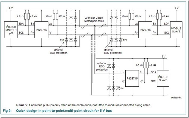
Following is a typical circuit example of how to implement this circuit:
Image from NXP P82B715 datasheet
It should be noted that while pull-up resistors are not really required for the Arduino boards over a small distance as implemented in part one, mainly because Arduino provides its own pull-up resistance, this is required for longer lengths.
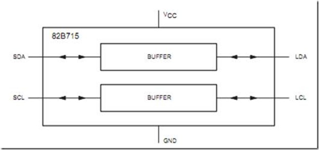
The extender chip basically serves as a current buffer. The standard I2C bus operates at 3mA, and this chip amplifies that to 30mA. What this does mean, however, is that two of these chips are required, one to push the current up to 30mA, and the other to bring it down to the 3mA level again. These chips are bi-directional so work well in this setup.
Image from the 82B715’s datasheet
The currents of 3mA and 30mA also define the values of resistance we can go up to. A value of 4.7k will use up about 1mA on the source side, so this value should not be exceeded. A value of 470 Ohms will use about 10mA on the buffered side.
The resistance values shown above can be used for the implementation of the circuit then.
While this bus has been tested up to about 11m on a shielded twisted pair Cat5e, theoretically this set up should work up to 30 meters.
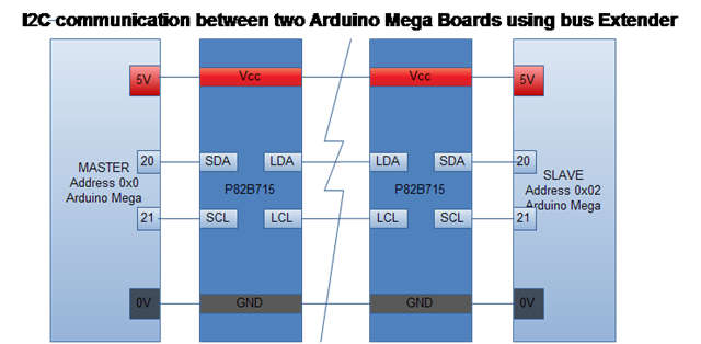
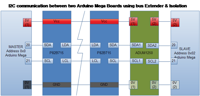
With the implementation of this, the circuit should look a bit like this:
Galvanically Isolating I2C bus
This is where things get a bit more complex. There may be many reasons to galvanically isolate a bus.
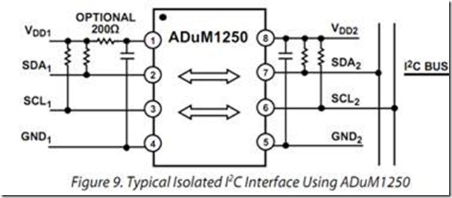
A device that was used in this example was Analog Device’s ADuM1250. A typical circuit is shown below:
Image from the ADum1250 datasheet
It is quite important to add the pull-up resisters, which are defined by the standard I2C bus, so values of 4k7 Ohms on either side should work quite well.
While this setup seems to work well, it was found that adding the isolation did make the bus a lot more sensitive to errors. Changes in hardware configuration from the specified (e.g. not having the pull-up resistors, and disconnecting) meant that the Arduino would go in to a hang mode, such that it would not even reset itself despite having a Watchdog timer built in to the software. The only way to get out of this is to power it down and power it up again. The reset button on the board does not work as well.
FYI, the hang mode that I state here, can be seen on the board because the ‘L’ LED starts to flash rapidly (10Hz).
Another thing that was discovered was that adding isolation somehow meant that the working length of the bus also somehow reduces itself. However, for the current configuration it still works up to 7 meters. This does mean however, that if this is being done over shorter distances, a bus extender may still be required to help overcome this issue.
Oscilloscope Readings of an I2C Bus
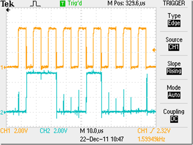
It is actually not very difficult to read what data is travelling on the I2C Bus if the signals are scoped.
The SCL Signal, as expected, is a uniform pulse, with bigger spaces separating every byte.
The SDA signal has one byte that dictates the send command and then the byte(s) are sent. Then, if that is how the code works, it has one byte that sends the receive command, and then the byte(s) are received.
This also means that if the bus was disconnected, the only bytes seen will be the send and receive command but no data shall be transferred.
Some images are as follows:
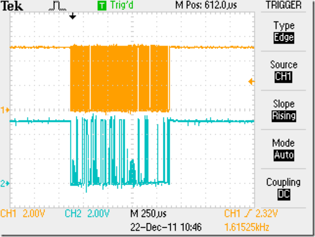
Zoomed out data sent and received.
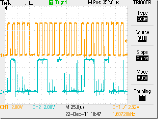
Zoomed in. The top shows SCL, which are uniform pulses, and a bigger space between bytes. The bottom shows SDA, which is quite literally a high for a 1 that is sent and a low for a 0 that is sent there. As can be seen, there are quite a few noise spikes there, but in this instance, the smaller spikes seem to get ignored and hence do not affect the communication.
Further zoomed in, focuses on a single byte.
Sources/Further Reading/Help Material:
Arduino Wire Library:
http://arduino.cc/en/Reference/Wire
Tronix Stuff I2C Part 1:
http://tronixstuff.wordpress.com/2010/10/20/tutorial-arduino-and-the-i2c-bus/
Tronix Stuff I2C Part 2:
http://tronixstuff.wordpress.com/2010/10/29/tutorial-arduino-and-the-i2c-bus-part-two/.
I2C Bus working, explanation and implementation:
http://www.gammon.com.au/forum/?id=10896
Detailed FAQ on I2C:
Datasheet for P82B715 (I2C Bus Extender):
http://docs-europe.electrocomponents.com/webdocs/009a/0900766b8009a3e8.pdf
Datasheet for ADUM1250 (I2C Bus Isolator):
http://www.analog.com/static/imported-files/data_sheets/ADUM1250_1251.pdf
(Updates: 04/01/12)
I2C Master Library:
http://dsscircuits.com/articles/arduino-i2c-master-library.html
Forum Discussing this Topic:
http://arduino.cc/forum/index.php?topic=84322

Why not just use serial communications. I don’t think it has the same distance limits.
I have tried serial as well. however, I did not get a chance to try it a lot.
With serial you have to establish your own protocol, whereas with i2c the protocol already exists. That was a very important factor for me.
it’s useful information to learn these for subject students so keep provide like these type blogs for more information great….
I second Sadia’s statments. I plan on using portions of this with my students as well. Sami, I can’t seem to find the master and slave sketches as a whole. Can you direct me to where they can be found.
Regards
Rick
Hi Rick,
Thanks for visiting the blog and commenting.
I do not have a sketch on me at the moment, but the block diagrams I have shown are quite literally all you need as long as you are connecting two arduinos together. There may be pull up resistors required, but the datasheets of the ICs should tell you about them.
Connecting two arduinos at a small distance is quite literally connecting the two pins together and making sure they are both powered.
If the circuit does not work, do give me a shout or email me, and I will try my best to help you.
Regards!
Hardware is not a problem, the diagram is great, thanks. Its the software sketchs that would be helpfull. Regards!
Oh I see! Sorry my bad, did not understand you.
I used http://www.gammon.com.au/forum/?id=10896 as a guidance to setting up the sketches and then making changes as required by your application.
Regards.
This comment has been removed by the author.
thanks rick.
Is it possible to use one extender on the master and one extender with serveral slaves connected on the remote extender or must each slave have an extender?
E.g you have a master 10 m away from a group of slaves within one meter between each other.
Theoretically yes, though you’ll have to try it and see, as I haven’t tried it at my end.
Thanks for a quick response. I have searched a lot to find anything like my demands. Your aricle is the closest I have got.
I will order some extenders and do a test. Will publish the result here when done.
Thanks. I look forward to it 🙂